|
NexMotion
1.4.0
Open Robots & Machines [WIP]
|
|
NexMotion
1.4.0
Open Robots & Machines [WIP]
|
The basic development procedure of the NexMotion application is described as follows:
The first 3 steps aim to confirm the following items:
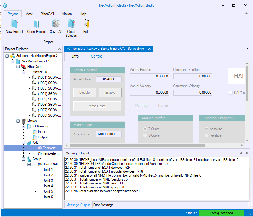
NexMotion Studio User Manual for the usage of the NexMotion Studio.After the above steps are completed, the configuration files will be generated in the default system path ( C:\\Nexcom\). The files in the path shall not be modified to avoid any undesired system The 4th step, develop the control program , indicates the control program developments based on the library provided by the NexMotion. The program can issue commands to the device by calling APIs to complete each applications. The following sections will describe the library functionalities systematically, including:
These classes of these APIs can be understood based on the naming rule of such APIs. For example: the APIs with the prefix NMC_Device are the System Operations class, the APIs with the prefix NMC_Axis are related to the Axis Control, the APIs with the prefix NMC_Group are related to the Group Control, and so on. Moreover, the extension applications can be developed by referring to the sample programs provided under the installation folder.
The section describes the following items:
The system initialization shall be performed before starting to use the NexMotion Library, the simplest way is to call the function NMC_DeviceOpenUp(). A device identification (ID) will be returned after the successful initialization, and it be used to control the device. A C sample program shows the system open up and shut down as follows:
NMC_DeviceOpenUp() is a blocked function. It will perform the system initialization processes, including:
The above processes may cost several seconds. After the function returns successfully, the following processes can send commands to the axes or groups. In addition, the Library also supports a non blocked function, NMC_DeviceOpenUpRequest(). The function can return immediately after called. The device can also receive the same commands and perform the above open up processes. After completing these processes, the device state will transfer to OPERATION , and NMC_DeviceGetState() can be used to check the state by polling or NMC_DeviceWaitOpenUpRequest() can be used to wait for the open up completion.
NMC_DeviceShutdown() can be used to shut down the device . After the function is called, the device will close communications immediately, so that users shall pay attention to the shutdown process . For example, users can call NMC_DeviceShutdown() to shut down the device completely after confirming all device motions are stopped.
The aforementioned procedure is easy and quick for the general initialization. However, some parameters may be configured before the system opens up. The system initialization can be achieved by separating the procedure as follows:
The separation initialization procedure shall call the 3 APIs in order:
The purpose is transfer the device state to OPERATION. The below figure shows the device state transitions and related functions.
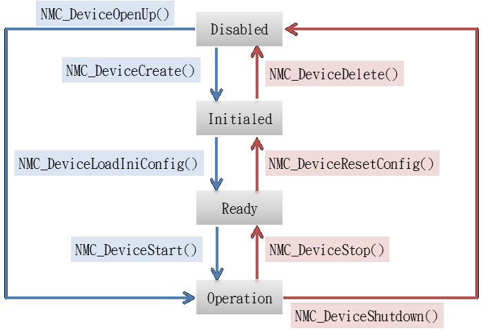
The device states can be getting by function NMC_DeviceGetState()
The watch dog timer is a dedicated timer of the device. After the timer starts, the application shall reset the value of timer within a specific period. Otherwise, if the timer reaches the configured time, the device will perform the corresponding actions for system shutdown automatically. The function is a protective measure to avoid the application crash or the system failure due to other programs. In case of the system failure, the device will enable the shutdown process because the timer is timeout when application cannot be reset and.
If the timer is enabled during the debugging phase of development stage, the debug process may interrupt the program. Some undesired ( cases may occurred since the timer is timeout and the system is shut down. Therefore, it is recommended to disable the function at the development stage and enable the function after the development completion f or additional protection. Generally, the watch dog timer is used by enabling a system timer interrupt or creating an independent thread. NMC_DeviceWatchdogTimerEnable() is used to enable the watch dog timer , and NMC_DeviceWatchdogTimerReset() is used to reset such timer. The reset may be two times or more as frequent as the configured time. NMC_DeviceWatchdogTimerDisable() is used to disable the timer.
An example is shown as follows:
To assist developers to debug the application, there are two measures, system messages and API trace.
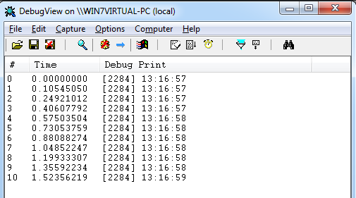
The system messages will be issued by the device during the operating and stored in the message queue. NMC_MessagePopFirst() can be used to get and remove the system messages from the message queue. To facilitate the debugging, NMC_MessageOutputEnable() can be used to copy the message and to transfer it to the MS Windows system message (OutputDebugString). Developers can download the tool, DebugView, to get the MS Windows system message from the website: https://docs.microsoft.com/zh-tw/sysinternals/downloads/debugview.
The API Trace can trace the calling of NexMotion Library by applications. NMC_DebugSetTraceMode() can used to enable the API Trace. The called function name, input parameters and return values can be output to MS Windows system message (OutputDebugString) in accordance with the configured Trace mode. Developer can observe the calling of NexMotion with the software, DebugView.
Moreover, a hook function (or a callback function) can be used to hook the self-defined function into the NexMotion functions. NMC_DebugSetHookFunction() can register the self-defined function into the system, and the NexMotion APIs will call the hook function before returning.
The registered hook function is global, and all called NexMotion APIs will call the same hook function. NMC_DebugGetApiAddress() can be used to inquiry the names of called APIs.
An example is shown as follows:
NexMotion provides flexible and high velocity I/O control as the memory access. Developers shall map the memory address of I/O devices onto the virtual memory with NexMotion Studio, and then they can control or get/set the I/O devices by accessing the memory. Please refer to the NexMotion Studio user manual for the configurations.
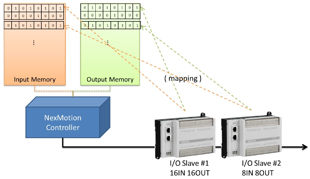
After configurations, the following functions can be used to access or control the I/O devices:
Note: The update rate of I/O memory is once per 10 ms (100Hz). Therefore, the functions may not support responses immediately if the frequency of digital output calling is higher than 100Hz.
Different from the group axis for coordination operations in the mechanism, the single axis described in the section is independent for the corresponding to the mechanical structure. Functionally, the contents of this section are mainly divided into three major parts. The first part is the axis configurations, including the unit and the software limit protection configurations. The second part is the motion control functions, including excitation, point-to-point motion JOG motion , stop motion and the change on fly function. Finally, the third part mainly focuses on reading the information related to the axis motion, including reading the current status and motion information of axis.
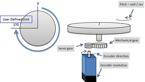
The required parameters set with the APIs for the axis motion, such as the position of point-to-point motion or the velocity of the JOG motion. These motions are operating on these units defined by users (user unit). To establish the relationships between these user units and the command counts actually set to the device, users shall set the related unit parameters first. The axis parameters related to unit configurations are listed in the below table:
| Param. Num | Sub Index | Description | Remark |
|---|---|---|---|
| 0x00 | 0 | Mechanical pitch (unit/rev) | (*1) |
| 0x01 | 0 | Mechanical revolution | (*1) |
| 0x02 | 0 | Motor revolution | (*1) |
| 0x03 | 0 | Encoder resolution (pulse/rev) | (*1) |
(*1) The parameter cannot be modified after the system is enabled.
The parameter mainly describes the user unit required for a mechanism revolution.
The two parameters must be set coordinately. They are used to describe the gear ratio relationship between the motor and the mechanism. For a rotating mechanism, there is usually a velocity reducer between the motor and the mechanism. Assume that the gear ratio of the velocity reducer is 80. It means that the motor rotates 80 revolutions while the mechanism rotates one revolution. Therefore, the 0x01 shall be set to 1 and the 0x02 shall be set to 80. For the linear mechanism with the lead screw, if there is only a coupling between the motor and the mechanism and there is no velocity reduction mechanism between them, the 0x01 and 0x02 shall be set to 1. However, if there is a velocity reduction mechanism between the motor and the mechanism, the 0x01 and 0x02 must be set in accordance with the gear ratio of the velocity reduction mechanism.
The parameter is mainly used to set the revolution of encoder. It represents how many pulse counts the encoder will return for a revolution of motor. For an encoder with a 20-bit resolution, the parameter shall be set to 1,048,576 because of $2^{20}$.
The unit conversion formula is as follows: $$ 1\ User\ unit\ =\ EncoderResolution {Motor\ revolution}{Mechanical\ revolution} Pitch\ (Pulse) $$
Unit configuration example 1: A disk mechanism
In an actual mechanism, there is often the travel limitation for an axis. Also, there are the position limit with positive/negative direction, the maximum allowable velocity and the maximum allowable acceleration in the axis parameters because of maximum output tongue and velocity limits for a motor. The motion control unit provides the software protection mechanism to ensure the mechanism is operating under conditions of the allowed limits during the axis is in motion. If the software limit protection is enabled, the motion parameters will be checked when an axis motion function is called. If the set limit conditions are not met, the function will return the corresponding error code. When a group is in motion, the device will stop if there is an axis exceeding the set limit protection. These parameters related to the limit protection are described as followed:
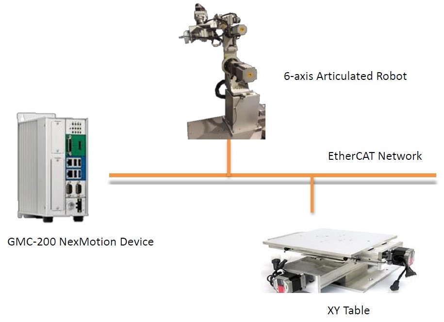
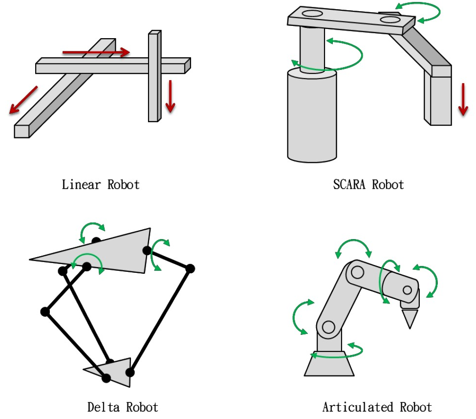
NexMotion can define some axes as a group. A group represents a mechanism or a robot with a specified structural relationship. Now, NexMotion can support these industrial robots as follows:
The mechanism configuration file can be imported with the NexMotion Studio through the steps as follows:
A group can also be defined by manual. First, a similar mechanism configuration profile can be imported with NexMotion Studio as the template. Then the related configurations of the template can be adjust/modified to meet the actual mechanism through the steps as follows:
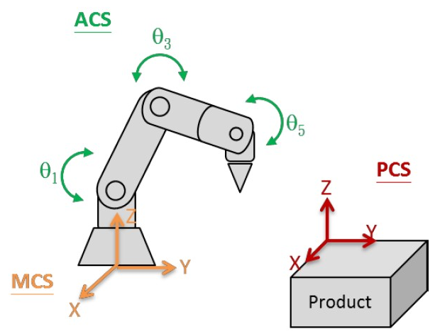
To control the position of each axis or each tool center point (TCP) in a group (or called a robot), NexMotion supports three coordinate systems to describe the position, including:
These coordinate systems are shown as the below figure:
NexMotion supports the built in unit conversion of these coordinate systems. Developers can define the conversions through the parameter configurations. The unit conversions of these coordinate systems are shown as the below figure.
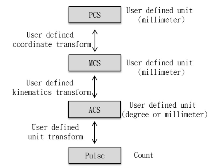
The parameters related to the conversions are described in the following table:
| Conversion Type | Parameter Type | Description |
|---|---|---|
| Unit Conversion | Group axis parameters 0x00~0x06 | Set the conversion between the pulse of servo and the physical unit of axis coordinate system (ACS) |
| Mechanism kinematics conversion | Group parameters 0x00 | Set the conversion between the axis coordinate system (ACS) and the machine coordinate system (MCS) |
| Coordinate system conversion | Group Parameters 0xC0~DF | Set the conversion between the machine coordinate system (MCS) and the product coordinate system (PCS) |
| TCP coordinate conversion | Group Parameters 0x80~8F | Set the conversion between the tool and the tool center point (TCP) |
NexMotion defines the data structure 「 Pos_T 」 and 「 Xyz_T 」 to describe the coordinate information. The Pos_T describes the coordinates of ACS, MCS and PCS, and the Xyz_T describes the positions at the x -, y- and z-axis of MCS and PCS.
Setting Base is to define the PCS coordinate system. The advantage is that all target positions are relative to the reference coordinate system (Base). When the reference coordinate system change, only the reference coordinate system needs to be reset, then the target position can be used without teach again.
The advantages of coordinate conversion of NexMotion PCS are as follows:
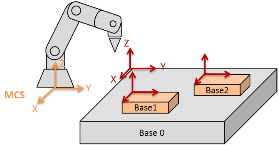
Base having a hierarchical set, as shown above, Base0 is relative to MCS, and Base1 and Base2 are relative to Base0. When Base0 changes, Base1 and Base2 will also change.
The setting method is to set the group parameter 0xC0 to 0xDF. Defined as follows:
| Param. Num. | Sub. Index | Data Type | Description |
|---|---|---|---|
| 0xC0 ~ 0xDF | 0 | F64_T | Offset along reference base x-axis |
| 1 | F64_T | Offset along reference base y-axis | |
| 2 | F64_T | Offset along reference base z-axis | |
| 3 | F64_T | Rotation angle about reference base z-axis | |
| 4 | F64_T | Rotation angle about reference base y-axis | |
| 5 | F64_T | Rotation angle about reference PCS x-axis | |
| 6 | I32_T | Reference base index |
For example: The coordinate origin of the Base (Index = 0) is 10 units of x-axis, 15 units of y-axis, 5 units of Z-axis with respect to the MCS coordinate system and the Base0 coordinate system is rotated 90 degrees with respect to the Z-axis of the MCS.
Group setting parameters and setting values are as follows:
| Num. | Sub | Value | Description |
|---|---|---|---|
| 0xC0 | 0 | 10 | Offset along reference base x-axis |
| 1 | 15 | Offset along reference base y-axis | |
| 2 | 5 | Offset along reference base z-axis | |
| 3 | 90 | Rotation angle about reference base z-axis | |
| 4 | 0 | Rotation angle about reference base y-axis | |
| 5 | 0 | Rotation angle about reference PCS x-axis | |
| 6 | **-1** | Reference base index |
If the motion command does not specifically specify the Base index, the system will refer to the group parameter 0x48:0 setting as the Base used by the current system.
| Param. Num. | Sub Index. | Data Type | Description |
|---|---|---|---|
| 0x48 | 0 | I32_T | Base index selection for motion target |
In addition to directly setting parameters, method of automatically calibration the teaching points is provided to set the Base. The automatic calibration methods include:
Corresponding APIs setting can refer to 3.4.14 Base Calibration Functions. As the name implies, 1p method only needs to teach one point. The 2p method only needs to pay two points. The 3p method needs to teach three points. Among them, the difference between the 2p method and the 1p method is that the base taught by the 2p method has more rotation of the Z-axis, and the 3p method can arbitrarily define the X-Y-Z axis.
| Param. Num. | Sub. Index | Data Type | Description | Range | Remark |
|---|---|---|---|---|---|
| 0x00 | 0 | I32_T | Motion cycle time (us). | 1000~4000 microsecond | (*1)(*3) |
| 0x01 | 0 | I32_T | Number of activated axis | 0~64 | (*1) |
| 0x02 | 0 | I32_T | Number of activated group | 0~64 | (*1) |
(*1): The parameter is effective after the system is started. During the system starting , the parameter cannot be modified.
(*2): The parameter is effective after the function is enable. The modification in another period cannot be effective immediately.
(*3): The configurable range is depended on the controller
(*4): Read only.
| Param. Num. | Sub. Index | Data Type | Description | Range | Remark |
|---|---|---|---|---|---|
| 0x00 | 0 | I32_T | Mechanical pitch (unit/rev) | 1~2147483647 | (*1) |
| 0x01 | 0 | I32_T | Mechanical revolution | 1~2147483647 | (*1) |
| 0x02 | 0 | I32_T | Motor revolution | 1~2147483647 | (*1) |
| 0x03 | 0 | I32_T | Encoder revolution (pulse/rev) | 1~2147483647 | (*1) |
| 0x04 | 0 | I32_T | Encoder direction | 0:Not inverse, 1:Inverse | (*1) |
| 0x05 | 0 | I32_T | Encoder type | 0:Incremental, 1:Absolute | (*1) |
| 0x06 | 0 | I32_T | Enable the encoder | 0:Disable, 1:Enable | (*1) |
(*1): The parameter is effective after the system is started. During the system starting , the parameter cannot be modified.
(*2): The parameter is effective after the function is enable. The modification in another period cannot be effective immediately.
(*3): The configurable range is depended on the controller
(*4): Read only.
(*5): The configurable range is depended on the controlled device.
| Num. | Sub | Type | Description | Value Description | Common |
|---|---|---|---|---|---|
| 0x00 | 0 | I32_T | Kinematics type | 0:Linear (2~8 Axes) 1:Articulated Robot (AR6) 2:Delta 3:SCARA | (*1) |
| 0x00 | 1 | F64_T | Kinematics parameter 1~48 | Refer to kinematics chapter | (*1) |
| 0x36 | 0 | I32_T | Buffer Mode | 0:Aborting 1:Buffered 2:Blending | |
| 0x36 | 1 | I32_T | Blending Mode | 0:Corner distance 1:MaxCorner deviation | |
| 0x36 | 2 | F64_T | Blending corner distance | pos unit, Value 0 to 2147483647 | |
| 0x36 | 3 | F64_T | Blending corner deviation | pos unit, Value 0 to 2147483647 | |
| 0x48 | 0 | I32_T | Base index selection for motion target | value = -1 :No base assignment (MCS) value = 0~31: base 0~31 | |
| 0x48 | 1 | I32_T | Base index selection for read position | value = -2 : Parameter disable value = -1 :No base assignment value = 0~31: base 0~31 |
(*1): The parameter is effective after the system is started. During the system starting, the parameter cannot be modified and will return error.
(*2): The parameter is effective after the function is enable. The modification in another period cannot be effective immediately.
 1.8.11
